All-in-one Roll Materials Cutting Machine
All-in-one Roll Materials Cutting Machine
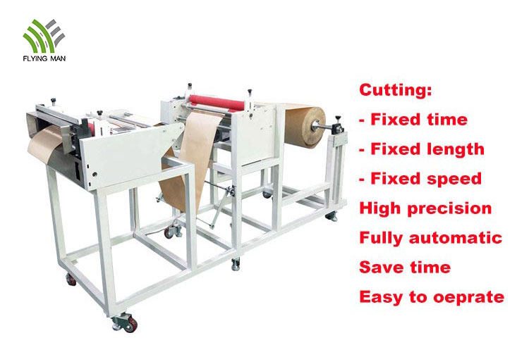
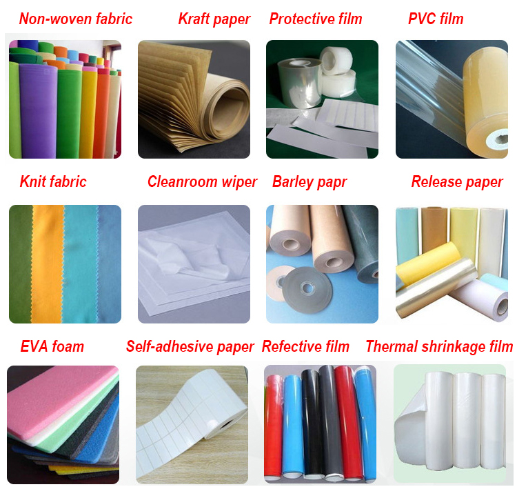
Flying Man all-in-one cutting machine can cut the width of 1-700mm, thickness up to 0.8mm of the materials, suitable for non-woven fabric cutting, aluminum foil cutting, copper foil cutting, reflective film cutting, plastic film cutting, Kraft paper cutting, etc. This automatic cutting machine is suitable to cut the wider width and wider diameter of roll materials. Increase the feeding drum, can straighten the material easy to fold, increase the feeding frame reduction gear, prevent processing too fast lead to the material roll because of inertia knotting and rolling to the ground, resulting in material breaking pull deformation, slip and scratch.
This cutting machine has different models#FMHZ-400A/FMHZ-500A/FMHZ-600A/FMHZ-700A, cutting width from 1mm to 700mm, cutting thickness is different. The maximum cutting thickness is 0.8mm.
Roll To Sheet Cutter,Film Cutting Machine,Non Woven Cutting Machine,Non Woven Fabric Cutting Machine Suzhou Flying Man Assembly Automation Co., Ltd. , https://www.flyingmans.com
Non-circular gear transmissions have appeared in the 1930s, but non-circular gears have not been widely used for a long time, and there is little information. The main reason is that the design calculation of the non-circular gear pair is complicated, the variety is various, and the shape is complicated, so the manufacturing process is also difficult. In recent years, computer hardware and software technology have been continuously developed, and the continuous popularization of CNC machine tools, the problem of difficult design and processing of non-circular gears will be gradually solved.
In the industrial field, AutoCAD is one of the most widely used excellent engineering graphics processing software. VisualBasic programming software is easy to learn and use, and it is an ideal development tool. Although VBA has been embedded in AutoCAD, its syntax, development environment and design concepts are almost the same as VB, and it runs faster, but considering VB is more powerful, such as with source code compilation, you can create ActiveX controls, support Database operations, can generate independent EXE executable files, etc., so I intend to use VB as a secondary development tool. On the other hand, familiar with the secondary development of VB, the use of VBA will also be effortless.
At present, there are researches on non-circular gear CAD in China, but the design result is often drawn by the drawing function of the programming software itself. The graphic thus drawn is not a vector graphic and cannot be recognized by the commonly used CAM/CAE software. Therefore, using VB to control AutoCAD to directly output design results can be easily imported into other CAM/CAE software, which is conducive to further work.
1 Mathematical Model 1.1 Section Design The determination of the non-circular gear section curve is the first and most critical step in designing a non-circular gear. In the actual design, the pitch curve is usually calculated in three ways, namely: given non-circular gear ratio function and center distance; given reproduction function and center distance; given the pitch curve equation and center distance of the driving wheel.
1.1.1 The center ratio of the given gear ratio function and the center distance gear pair is a, the rotation angle of the driving wheel 1 is 1 gear ratio function 1.1.2 The given reproduction function and the center distance setting require a non-circular gear transmission to reproduce a function. In most cases, the pitch curve of the non-circular gear pair used to reproduce the function is not closed. For this type of gear, according to the cutting conditions.
1.1.3 Given the pitch curve equation of the driving wheel 1 and the center distance setting, the center distance a of the gear pair and the driving wheel 11.2 cutting the cutting tool or the gear shaping tool for the non-circular gear, and Similar to the machining of circular gears, undercutting may also occur. The radius of curvature of each point on the non-circular gear section curve is different, and the root cut is most likely to occur, of course, the part with the smallest radius of curvature of the section curve. For the calculation formula of the radius of curvature, you can refer to the relevant data of differential geometry.
When a non-circular gear is machined with a rack cutter, the condition of the undercut is the same. When the non-circular gear is machined with a gear cutter, the condition of the undercut is not set to 1.3. Yes: 1.4 Convexity Verification When there is a concave part on the curve of the section, it is usually not possible to use a hob to cut the teeth and apply the shaper cutter. Therefore, when designing a non-circular gear, the joint curve must be convexly verified. The condition that the concave curve does not appear in the pitch curve is that the radius of curvature of the entire section curve is greater than zero. When a given gear ratio function 2 design process and results are given below, given the reproduction function and center distance as an example, the design process.
Some design examples and their results are given for the generation of the above three pitch curves.
(1) The given gear ratio function is: The maximum rotation angle of the driving wheel is 280°, and the maximum rotation angle of the driven wheel is 300°.
(3) Taking the n-order ellipse as an example, the equation of the pitch curve given the driving wheel is: a is the long axis radius, e is the eccentricity, and n is the elliptic order.
Let a=50, e=0.6, n=1, center distance A=100. In order to clearly see the meshing condition of the elliptical gear pitch curve, the active wheel angle is now given at 0°, 60°, 120°. Elliptical gear pair, see Figure 4.
3 Summary Through the organic combination of VB and AutoCAD, the design calculation of the non-circular gear section curve is simple, and the result of the design can be displayed dynamically and intuitively, and the problems can be corrected in time and conveniently. The completion of the CAD design module of the curve provides the necessary preconditions for subsequent work, such as tooth design, 3D modeling, finite element analysis, machining simulation, etc., which lays a good foundation for the extensive use of non-circular gears. .
The transient temperature distribution simulation of the mold and plastic parts cooling process was carried out by ANASYS. From the simulation results, we can visually see the temperature change process of each part of the mold. We can know the transient temperature value of each node at each moment, judge the cooling effect, and verify the rationality of the distribution of the cooling water pipe. According to the cooling condition of the plastic parts, the holding pressure period (determined here as 60s) can be determined, and the result is basically consistent with the empirical value.
Of course, this paper simplifies the model (takes 1/4 model) when processing, so as to save computer resources. Ignore a few conditions that do not play a key role, such as the elimination of a very small flow path plastic part. These processing methods are permissible in engineering, but there is often a slight error in the accuracy of the results. If you use a large computer, you can not simplify it, and the results will be more accurate.

