S6829,Basketball shooting training equipment; basketball shooter machine; basketball serving machine Yi He Technology (Shenzhen) Co.,Ltd , https://www.nbball-shootingmachine.com
Key words: water injection profile, flow meter, ultrasonic, production logging, logging technology 0 Introduction Through analysis of three-parameter water injection profile logging data of domestic water injection development oil fields in recent years, the main problems are: the gamma background height , serious contamination, large test resistance, large formation strata, wellbore and string leakage, etc. In addition, due to the complexity of the water injection column, the understanding of the downhole water flow is not clear, and it is impossible to analyze the work of the water distributor, packer and other tools. The situation has affected the application of data [1, 2]. For complex water injection wells, multi-parameter and diverse water surface logging techniques must be developed to meet the development needs of the oil field.
1 Ultrasonic Flowmeter Logging Technology 1.1 Measurement principle Ultrasonic phase difference principle is adopted. Two ultrasonic sensors with similar characteristics A and B are designed. The distance is L. As shown in Figure 1, the ultrasonic frequency is f and the wavelength is λ. Velocity of sound V = f × λ, wave number N = L / λ = L × f / V, because L, f is a constant, then N and V are inversely proportional. 
The phase difference Δb = Δn × 360o = 720oL × f × U / (V2-U2), because V >> U, then △ b » 720oL × f × U / V2, because L, f, V is a constant, then The phase difference Δb and the fluid flow velocity U have an approximately linear relationship.
Therefore, when the ultrasonic phase difference Δb is measured, the fluid flow rate U can be calculated, and the flow of the known inner diameter of the pipe can be calculated.
1.2 Instrument features Logging items: magnetic positioning, gamma, well temperature, pressure and ultrasonic flowmeter five-parameter combination logging.
Instrument Index: Outer Diameter 38mm, Total Length 4.5m, Temperature Resistance 150°C, Pressure Resistance 70MPa, Measuring Range 0~370m3/d in 2.5in (1in = 25.4mm) Tubing, Measurement in 5.5in Casing The range is from 0 to 1800m3/d.
Scope of application: It is applicable to layered injection wells with an inner diameter greater than 40mm, empty wellbore, and general injection wells with bells in the upper part of the perforation section.
1.3 Construction method Ultrasonic flowmeter is combined with magnetic positioning, gamma, well temperature, and pressure to enter the well. Shut the well for about 2 h to 4 h. Measure the well temperature, gamma, magnetic positioning, and pressure when the injection well is relatively stationary. Normal water injection is resumed. After stable, isotopes are released in the upper part of the perforation layer. After the isotope is well distributed, at least two isotopes, well temperature, pressure, magnetic positioning, and ultrasonic continuous curves are measured. Then, the measured ultrasonic waves are measured. The continuous curve and the water injection pipe string are about 200m from the wellhead, about 10m above and below the water distributors, about 10m above and below the ultrasonic well, and about 2m below the perforation interval. Resistance point of about 5m on the measurement of ultrasonic fixed-point flow, fixed-point measurement time is not less than 120s. If there is a significant fluctuation in the ultrasonic fixed-point flow curve, or if the abnormal flow occurs in the water flow calculated from the ultrasonic fixed-point flow value check chart, repeat the fixed-point verification.
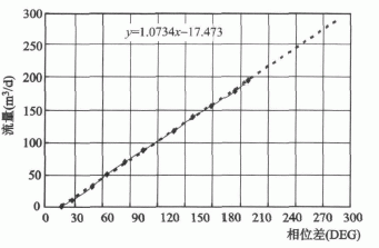
2 Interpretation method 2.1 Explain the plate Before the instrument is put into use, perform flow calibration and calibration in the standard tubing and casing, make an interpretation plate according to the calibration value, and use the least squares method to return the formula between the flow and phase difference. Figure 2 shows. If the instrument is used for a long time and zero drift occurs and the error is large, scale and calibration must be performed again. 
2.3 Calculate layered water absorption [3]
Firstly, the evaluation section of the perforation layer, the upper and lower parts of the water distributor, etc. are selected, and the flow in the tubes of each evaluation well section is calculated according to the method of 3.2 according to the ultrasonic fixed point or continuous phase difference. Permeability of the perforation layer or water in the water dispenser.
For stratified water injection wells, if the sealer is in good condition, the perforation layers are divided into several interpretation units according to the injection well intervals. The actual water injection amount of each water distributor is first calculated according to the ultrasonic flow curve, and then isotope water absorption is performed. The size of the area, accurately assess the water absorption of each layer. Its characteristics: can check and accurately calculate the actual allocation of the water dispenser; combined with multi-parameter analysis, you can accurately determine the packer seal.
For general injection wells, if the interval between the perforation layers is large (generally greater than 2m), the ultrasonic flow curve has significant changes between the layers, which can be directly interpreted according to the flowmeter curve. If the interval between the perforation layers is small and the flowmeter curve does not change significantly between layers, these perforation layers can be divided into one interpretation unit. Based on the flow curve, the total number of stratigraphic elements along the large hole can be calculated from the flow curve. The amount of water absorbed, and then it is based on the size of the isotope water absorption area, accurately assess the water absorption of each small layer. For the trenching phenomenon, the layers in the trenching section are divided into an interpretation unit. The total water absorption of the unit is calculated using the flow curve, and then the suction of each small layer is accurately evaluated according to the size of the isotope water absorption area. the amount.
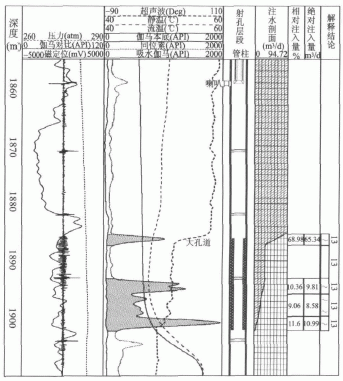
3 Application example analysis 1) When large pore channels exist in the local layer of large pore formations, the diameter of conventional isotope carriers is smaller than the diameter of the pores, and they will enter the deep layer of the formation with injected water, resulting in less difference between the measured isotope curve and the gamma background. Even if there is no difference, only interpreting the water absorption of the small layer based on the isotope curve will result in a large difference from the actual situation. If combined with an ultrasonic flow meter, it can well reflect the actual water absorption of the formation. For example, the water absorption profile measured on GX110-7 well on October 21, 2009 is shown in Figure 3. The water injection interval of this well is No. 13 layer, the perforation interval is 1886.0m~1902.0m, and the thickness is 16.0m. To 1859.4m, water injection pressure of 9.0MPa, water injection volume of about 100m3/d, the use of isotope carrier particle size 300μm ~ 600μm, particle density 1.02g/cm3. It can be seen from the figure that the isotope tracer curve has weaker water absorption at the top of the 13th layer (1885.3m~1887.3m), and the interpreted water absorption accounts for 23.52%, but the ultrasonic flow curve has a significant anomaly here. Explanation The amount of water absorbed accounts for 68.98%, indicating that there are large holes and large depths. 

The L90-** well is a water injection well with a water injection interval of Es2+3, a water injection well section of 2629.0m to 2666.8m, and a 13.2m/4 story. The well is a general waterflood with a daily injection volume of 100m3/d. On April 11, 2010, the well was subjected to isotope water injection profile logging. In the process of construction, the logging instrument was blocked at 2662.0m, and the last layer was not measured. The water absorption of the constrained layer was analyzed from the monitoring curve. Therefore, on-site construction personnel contacted the geologists in time and switched to ultrasonic flowmeter logging. As shown in Figure 5, the absorbed water of the confined layer accounted for 95.49% of the total well water injection volume calculated from the ultrasonic flow curve, giving full play to the ultrasonic flowmeter. Advantages provide reliable logging data for oil production plants. 
4) Check the actual allocation of water dispensers In the stratified injection wells, different sizes of water distributors are designed for different layers. The water nozzles are expected to be filled with water as planned. If you want to check the actual water injection conditions of each water dispenser, ultrasonics can be performed. Flow meter logging. The L1-* well is a water injection well with a water injection interval of Es32+3 and a water injection well section of 2516.0m to 2646.8m. The current water injection method is two-stage, three-stage injection, with three water distributors and two packers. Wellhead water injection capacity About 106m3/d, the water distributor 1 was designed as a dead nozzle, the water distributor 2 was not a nozzle, and the water distributor was 3 shot 60m3/d. On April 11, 2010, ultrasonic flowmeter logging was performed. The water distributor 1 did not absorb water. The water intake of the water distributor 2 was 58.27 m3/d. The water intake of the water distributor 3 was 48.00 m3/d. The test results were basically consistent with the actual filling conditions. .
4 Conclusion Ultrasonic flowmeter can identify large pore and micro-fracture strata in the water-injection profile logging, reveal the contradiction between layers, check the working conditions of downhole water injection string, determine the loss of shallow casing, and increase the natural gamma background height Logging success rate and interpretation accuracy of the water-injection section of the YZM well solved many problems in the common isotope water injection profile logging technology.
References [1] Junjun Li, Zhuokan Xi. Flow logging technology for water injection profiler in complex injection wells[J]. Petroleum Instruments, 2005,19(6)
[2]Wang Xiang, Xia Zhujun. Research on the identification of large pores using water logging profile logging data[J]. Logging Technology, 2002, 26(2)
[3]Xia Zhujun.Evaluation of external gutters using pulsed neutron oxygen activation logging technology[J].Natural Gas Technology,2008,23(2)
Application of Ultrasonic Flowmeter in Water Injection Profile
Abstract : The paper introduces the logging principle, instrument characteristics, construction process and interpretation method of ultrasonic flowmeter, and analyzes the technology in identifying large pore strata, inspecting downhole tubular conditions, judging casing leakage, and improving the accuracy of water injection profile interpretation. The application of a large number of actual logging data shows that the ultrasonic flowmeter solves many difficult problems of water injection profile logging.
Fig. 1 Schematic diagram of the measurement model of the flow sensor
When the fluid flows in the direction of A→B at velocity U, the speed of the forward flow is Va=V+U, the speed of sound at the counter-current Vb=VU, then the number of waves at the time of flow is Na=V×n/(V+U), and the number of waves at the time of counterflow is Nb= V×n/(VU), when the ultrasonic wave is transmitted in the forward and backward directions, the difference between the positive and negative flow wave numbers in the L distance is: Δn=Nb-Na=n×2U×V/(V2-U2), where n=L×f /V, then Δn=2L×f×U/(V2-U2). Figure 2 Ultrasonic Flowmeter Calibration Plate in 2.5in Tubing
2.2 Calculate the flow rate in the evaluation well section According to the phase difference value of the ultrasonic fixed-point flow or continuous flow, the flow rate can be calculated by substituting the regression formula as shown in Figure 2. The flow calculated based on the fixed-point phase difference does not contain the well logging velocity. Influencing, the calculated flow directly reflects the actual flow of fluid in the pipe at the fixed point depth; and the flow calculated from the continuous phase difference contains the effect of logging speed, and the flow calculated by the continuous phase difference in the stagnant water at the same speed is required to be able to The actual flow of fluid in the pipe at this depth is reflected. Fig. 3GX110-7 Well Ultrasonic Flowmeter Water Injection Profile
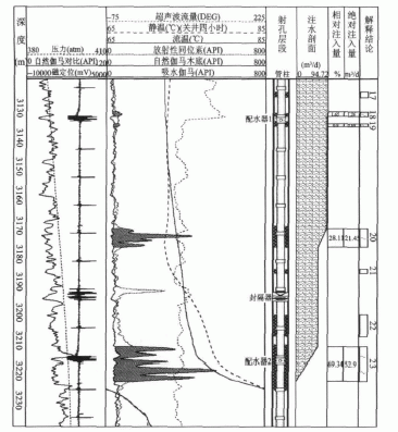
2) Check the packing effect of the packer In the layered injection well, the ultrasonic flowmeter curve can be measured to accurately determine the packing effect of the packer. For example, the L15-** well is a water injection well with a water injection interval of Es33, a water injection well section of 3079.6m to 3082.3m, and 40.0m/8 floors. The well was divided into two levels, the upper one was 80m3/d, and the lower one was not. On April 9, 2010, an ultrasonic flow meter injection profile logging was performed. As shown in Figure 4, from the isotope curve analysis, the upper and lower sections of the packer showed water absorption, which was basically consistent with the design of the injection. However, the ultrasonic flow curve shows that all the injected water enters from the upper nozzle, a part of the water enters the perforation layer at the upper part of the packer, another part of the water enters the lower perforation layer through the packer, and the lower nozzle does not enter the water. Packer failure. Figure 4 Water injection profile results of ultrasonic flowmeter in L15-** well
3) Improve the accuracy of water-injection profile interpretation of YZW wells. In long-term water-injection profile logging construction, it often encounters phenomena such as casing deformation, tubing not in place, plugging of downhole tools, and falling or sinking sand on the bottom of the well. Isotope water injection When profile logging interpretation, some wells can not qualitatively analyze whether the constrained layer absorbs water, and it is impossible to quantify the amount of water absorbed by the constrained layer. The conventional treatment method is: the amount of water absorbed by the constrained layer is not considered in the quantitative interpretation, thereby affecting the water absorption of the well. The quantitative interpretation accuracy of the layer. If the ultrasonic flowmeter logging is performed, it can not only accurately analyze the water-absorbing condition of the constrained layer, but also improve the quantitative interpretation accuracy of the well. Figure 5 Water injection profile of L90-** well ultrasonic flowmeter