Nickel Based Laser
Cladding Powder
Ni base alloy
powder is mainly made of NiCrBSi or NiBSi. Ni-based self-fluxing powder has
good wettability, corrosion resistance and high temperature self-lubricating
effect, and is used in components with heat resistance, corrosion resistance and
thermal fatigue resistance. In general Ni35,Ni45,Ni60 etc can be used for laser
cladding, the No means hardness of powder. Inconel 625 and 718 has good
corrosion property under higher temperature, also widely used for laser
cladding process.
Cobalt based Laser
Cladding Powder
Cobalt-based alloy
powder is the cemented carbide resistant to various types of wear and corrosion
as well as high temperature oxidation. That is, the so-called
cobalt-chromium-tungsten (molybdenum) alloy or Stellite alloy cobalt-based
alloy is mainly composed of cobalt, containing a considerable amount of nickel,
chromium, tungsten and a small amount of molybdenum, niobium, tantalum,
titanium, Alloying elements such as lanthanum, and occasionally a class of
alloys containing iron.
Co-based self-fluxing
alloys have good high temperature performance and wear resistance and corrosion
resistance, and are used in petrochemical power, metallurgy and other
industrial fields where they are wear-resistant, corrosion-resistant and
high-temperature resistant.
Iron based Laser
Cladding Powder
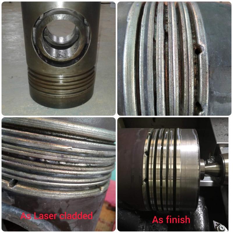
The work pieces
required for laser cladding and manufacturing in the actual industry are mainly
carbon steel and cast steel. The Fe-based alloy is close to the base material
in composition and has good wettability. The advantage of Fe base powder is
lower cost and good wear resistant of cladding layer. As a result, it`s the
most widely used for laser cladding process. It is suitable for parts that
require local wear resistance and are easily deformed.
WC blended Laser
Cladding Powder
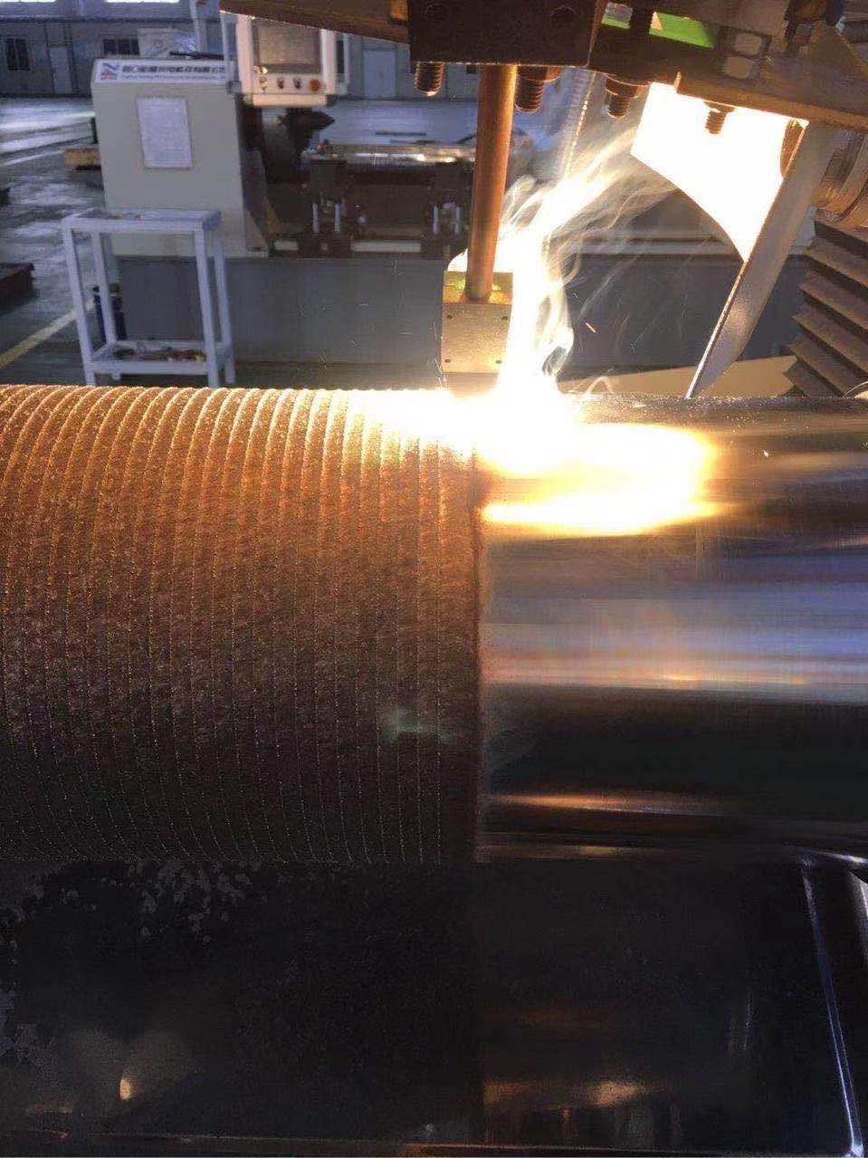
Tungsten carbide blended with Ni alloy powder is the best
choice for wear resistant work piece. This unique process can bring excellent
wear, corrosion and high temperature resistant. Our blend powder can achieve
different portion of WC from 35% to 60% without crack under suitable cladding
parameter.
Iron Alloy Powder,Nickel Alloy Powder,Cobalt Alloy Powder,Laser Cladding Powder Luoyang Golden Egret Geotools Co., Ltd , https://www.hvofpowders.com
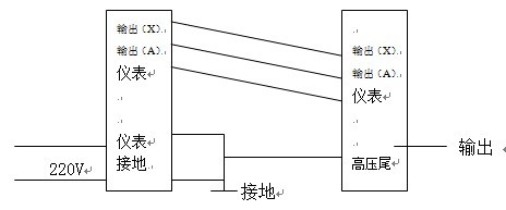
1, according to the wiring diagram to connect the working line, it must be noted that the use of the test transformer must be "high voltage tail" and reliable grounding. 
2. Before turning on the power, adjust the regulator of the operation box (Taiwan) to zero. After the power is turned on, the green indicator light is on, the start button is pressed, and the red indicator light is on, indicating that the transformer is powered on and waiting for boost.
3. Rotate the pressure regulator handle clockwise with a speed of 1.5-2KV/S, and pay close attention to the meter indication and the condition of the tested product. When the leakage current is too large or the test product is broken down, overcurrent protection The relay will quickly cut off the power supply.
4. After the oil-immersed test transformer is completed, adjust the pressure regulator to zero at a uniform speed.
5. If the voltmeter pointer is found to be oscillating during the test, the current meter indication value increases sharply, or the sample smokes, arcs, has a focal position, and abnormal noise, the voltage should be immediately depressurized, cut off the power source, and check the cause.
6. When the oil immersed test transformer is used for DC test, the high voltage test transformer shall loosen and loosen the silicon stack short circuit rod (D) and the series tapping terminal rod (C) in the high voltage sleeve, and wrap it with clean insulation paper. When conducting the AC voltage test after the DC test, two shorting rods must be screwed.
7. Current limiting resistors and filter capacitors should be added to the DC test to prevent damaging the silicon stack.
8, the environment; temperature is too high, the top of the casing may have a small amount of oil overflow, is a normal phenomenon. When the DC test, if the corona on the inner wall of the casing appears obvious, it is generally a phenomenon of low oil. At this time, the shorting rod should be taken out, and the qualified 25# transformer oil should be supplemented with a syringe from its hole.
9. When the test transformer is used in series, the high voltage test transformer must pay attention to the corresponding contact between the output terminals (A) and (X) of the operation box and the output terminals (a) and (x) of the first test transformer. The first test transformer The output terminals (A, X) are connected to the test transformer input terminals (a) and (x) on the second JT1. The housing of the test transformer should be connected to the input of the primary transformer, and the input terminal of the test transformer on the third JT2. (a) and (x) are connected to the top output terminals (A) and (X) of the test transformer bushing on the second JT1.
For more information, please contact us


Explain the wiring method of high-voltage test transformer
Explain the wiring method of the high voltage test transformer: