The vertical movement of the sucker rod or the cable drives the downhole piston pump to work. From the traditional beam development to the tower type rod pump, it is a widely used manual lifting device. An article in the April issue of the United States "World Petroleum" magazine describes four new types of equipment and devices developed and applied by four U.S. companies. Recently, the United States, Texas, Harbison Fischer company through experimental research, completed a unique sucker rod suspension tool. When the pumping well needs to lift and lower the tubing, the pump is lifted, the suspension tool is screwed onto the top of the sucker rod (on the ground), lowered and screwed into the oil outlet tee. The tool is equipped with a built-in fitting to lift the sucker rod and push it into the oil tee. Rotary union can also be added to rotate the sucker rod without rotation. Seal the wellbore during installation, and then lift the tubing string to be safer than conventional suspension tools. The new suspension tool conforms to the Uncured Steel Code of Practice developed by the American National Institute of Anticorrosion Engineers and is available in several universal sizes. Low-profile pump A new pump, Dynalow, developed by Dyna Pump Inc. of the United States, is a low profile pump that has the same features and functionality as the company's previous DynaSave pump. Its fixed height of less than 3 meters, the maximum stroke of about 1 meter. The pump is designed for use in farm irrigation systems and weighs less than 635 kg for safe operation. Calculate wellhead pressure with pump downhole diagram Stop pump controller has developed into a full-time power meter. Currently, computers used in mines can accurately measure load, position, and pressure, temperature and capacity. As a function of position, this technical improvement requires accurate plane load measurement. Oil well automation managers in Houston, U.S.A can not only calculate the dynamometer for each stroke of the downhole pump accurately, but also calculate the wellhead pressure of the pump. The starting point for managing flow areas and pressure support is quite important. The data entered by the dynamometer includes the fluid load, the total stroke, the net stroke and the movement of the tubing. Fluid Loading The drawing chosen is different in the upper and lower load lines on the dynamometer. Fluid loads can not include friction and inertia of the fluid. Ideally, due to the same buoyancy, the load line must be lowered below zero load. The accuracy of buoyancy calculations depends on accurate load measurement, design parameters of the sucker rod, and inclination of the tubing fluid (gradient). Through the entire input data, pump inlet pressure can be calculated. During the calculation, other required information can also be displayed. Replace the rod with cable A new oil well pumping system that replaces sucker rods with cables is being developed and tested by Taylor Pumps Inc., of Texas, USA. The system uses steel cables instead of sucker rods and ground tower lifting devices to replace the oil pumping racks. The pump lift attached to the cable is computer controlled. A new tool to reduce airlocks and pumps has been developed and tested and patented. Under the new drainage tool into the bottom of the pump, tubing can be drained when needed. The newly developed two tools are used for tubing anchor (suspension) displacement and chemical measurement points. The new tool can increase production of crude oil with less impulse and longer stroke per minute, producing 24-hour airless lock, using computerized control of the system to keep the surface of the annulus liquid optimized. This control can be replaced by lifting pressure instead of tension , Real-time measurement, and each stroke can send instructions to the computer. The economic value of new tools is recognized when repaired. This particular cable is rolled up, the downhole pump assembly is repaired, and then it is returned to the bottom of the well without the need for workover equipment. The pumping method for this tool is in the early stages of testing and will be applied to the field in the near future.
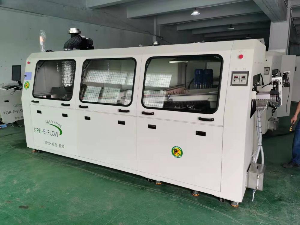
Wave-Soldering Machine used to Electronic production line. Our wave soldering machine Effectively improve product quality and production efficiency.
Closed loop
with inverter control system to keep the stability and accuracy of the conveyor
speed
The assistant
pressure device nearby the entrance to prevent the PCB from slipping:
Spray nozzle
driving by stepping motor is to make sure the coating uniformly;
Module design
of spray fluxer system and the design of nozzle always be perpendicular to
rail, which can make sure the flux penetrates PCB easily
Forced air
cooling system to attain the cold-down slope as per lead-free required
Conveyor angle
can easily be adjusted by manual:
Standard with
hot air heating for preheating zones.
Module design
suitable for SMT THT component soldering
Exhaust adopt
centrifuagal fan with double filters to avoid any flux drop to PCB
The level of
flux container is controlled by non-contact sensors to ensure no
Corrision and
longer lif
Flux spray
nozzle with self-cleaning system
Standard with
air knives to prevent flux expand to preheat zone
Wave height
control adopted with inverter, it can be set individually
1/4HP high
power mechanical pump to meet the wave as high as 15mm
Light Sound
alarm, Emergency stop and over-load protection
Wave-Soldering Machine,Automatic Wave-Soldering Machine,Wave-Soldering With Short Time,Efficient Wave Soldering ROC Precision Intelligent Technology Co., Ltd , https://www.electronic-smt.com
Hanging tools
