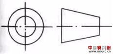
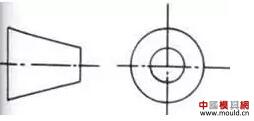
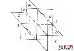
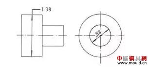
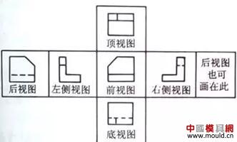
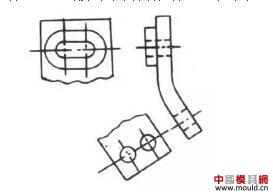
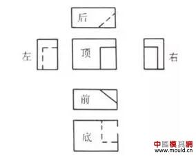
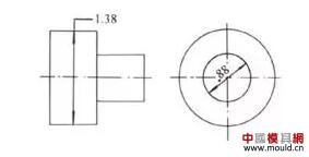
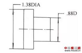
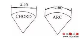
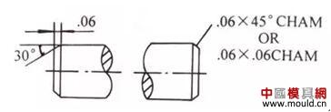
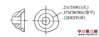
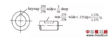
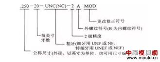
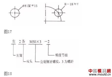
Since the reform and opening up, China has imported a lot of foreign equipment, drawings and other technical materials, and many of the developed countries have different methods of mechanical pattern projection than those used in China. In order to better learn the advanced technologies of developed countries, it is necessary to quickly understand foreign mechanical drawings. 1 Overview In the world today, ISO international standards stipulate that the first angle and the third angle projection are equally effective. All countries have focused on national conditions, among which Russia, Ukraine, Germany, Romania, the Czech Republic, Slovakia, and Eastern Europe all use the first projection, while the United States, Japan, France, the United Kingdom, Canada, Switzerland, Austalia, and the Netherlands Mexico and other countries use mainly the third projection. Before the liberation, China also adopted the third projection. After the founding of New China, the first projection was used. In the introduction of foreign mechanical drawings and scientific books and periodicals often encounter the third projection. The ISO International Standard specifies the projection marks for the first and third corners (Figures 1 and 2). In the title bar, mark symbols are drawn, according to which symbols can be identified, but some drawings have no projection marks. Figure 1 The first corner mark symbol Figure 2 The third corner mark symbol 2 Third angle projection The space can be divided into eight regions by a positive plane V, a horizontal plane H, and a side plane W, which are the first, second, third, fourth, fifth, sixth, seventh, eighth sub-angles, respectively, as shown in the figure. 3 shows. image 3 2.1 Projection of objects in the first sub-angle is called the first angle projection, also known as E method - European method. 2.2 The projection of objects in the third sub-angle is called the third-degree projection, also known as Method A - the United States. Our country uses the third projection method. The third angle projection is a method of imagining that an object is placed in a transparent glass box and each side of the glass box is used as a projection surface, and an orthographic projection is obtained according to the position of the person-face-object, and the method is shown in FIG. 4 and FIG. 5 . Figure 4 Figure 5 2.3 The position of the six basic views in the third angle projection According to ISO International Standards, the positions of the six basic views in the third projection are shown in Figure 6. Figure 6 The above view is obtained by projecting an object onto the respective projection surfaces of a "transparent" "projection box". Each view can be understood as the actual image of the object he sees when the viewer's line of sight is perpendicular to the corresponding projection plane. The front view is the observer's assumption that he is in front of the object and moves the position of the eye point by point, and the line of sight is always perpendicular to the frontal projection of an imaginary front projection surface (transparent). Other views can be similarly displayed. obtain. The viewer should always regard the view as a side of the object itself. From the front view you can see the height and width of the object, as well as the position of the top, bottom, left and right sides of the object. The top view shows the depth and width of the object. 2.4 Advantages of the Third Angle Projection (1) The view configuration is better and it is easier to read the map Views directly reflect the direction of view, easy to see, easy to map. The left view is on the left and the right view is on the right. The first angle projection sometimes uses "view to view" to compensate for unclear parts. (2) It is easy to imagine the spatial shape of the object The left and right views are inward and the top view is downward, which makes it easy to imagine the shape of the object. (3) Easy to draw axis diagram It is easy to imagine the spatial shape of the object, and it has a direct help in imagining the shape of the object when drawing the side view of the axis. (4) Helps to express part details Adjacent maps nearby Configuration, generally do not need to be annotated, as shown in Figure 7. (5) Size and other labels are relatively concentrated. 3 Comparison of the widths of maps in some major countries (Table 1) Table 1 4 Introduction of several national machinery drawing standards 4.1 American Standard (ANSI) The United States only stipulates that it should use the first trigonometry (occasionally, it should also be projected on the architectural and structural drawings with the first angle, but it must be specified). There are two types of view layouts, the first being the same as the ISO international standard, as shown in Figure 6. The second type is shown in Figure 8. Figure 8 In the US standard, the dimensioning method: The dimensions in the United States drawings are seldom measured in mm and generally use inches (1 inch = 25.4 mm). The original fraction is used to indicate how many inches, such as 9/16 inch, etc. Decimal, written in decimal form. When the value is less than 1, do not write 0 before the decimal point, the number of recommended horizontal writing. Tolerances of the tolerances must be the same as the basic size. For example, if the dimension is greater than 6 feet, the inch in inches should be noted, such as "12'7". (1) Diameter, radius, ball code 1 When the view is clearly reflected as a circle, do not note the diameter code DIA (diameter) or D, as shown in Figure 9; when there is only a non-circular view, the dimension figure is filled with the diameter code DIA or D, as shown in Figure 10. Figure 9 Figure 10 2 After the radius dimension number, the radius R (radius) is not added. When the radius dimension is in the view that does not reflect the radius and the arc solid, the radius dimension number is required and the TRUER (TRUE RADIUS) code is added (true R). . The sphere code is coded with SPHERR DIA (ball diameter) or SPHERR (sphere radius) after the dimension number. (2) Chord (COR) and arc length (ARC) injection methods are shown in Figure 11. Figure 11 (3) Chamfer CHAM (CHAMBER) is shown in FIG. Figure 12 (4) Counterbore as shown in Figure 13. Figure 13 (5) Keyway Figure 14. Figure 14 (6) The thread mark is shown in Figure 15. Figure 1 This article describes the difference between foreign mechanical drawings and domestic mechanical drawings (2). 4.2 Japanese Standards (JIS) The method of representation of drawings is similar to that of the United States. Generally, the third projection method is used. In principle, the same drawing must not be mixed with the first angle and the third angle. If necessary, the two types of paintings can be mixed locally, but they must be shown with arrows. The direction of projection of a painting. Japanese standard dimensioning method: (1) Diameter, radius, square, ball code When there are diameters, radii, squares or spherical diameters and radii in the figure, “φâ€, “Râ€, and “□†are added before the size figures. When the figures are clear, φ, R, and â–¡ can be omitted. (2) Chamfering Generally the same as our country. For a 45° chamfer, the letter “C†can be used. As shown in Figure 16, C2 is equivalent to 2×45°, and C3 is equivalent to 3×45°. (3) When the thickness is not drawn, the letter “t†can be added, as shown in t10 in Figure 16, which is equivalent to δ=10 in our country. (4) Use “P†to indicate rivet hole spacing, eg: P=100, P=98 (indicates hole spacing is 100 or 98). (5) The size of the hole can represent other contents 1 blind hole, as shown in figure 17. The description of the processing method is usually indicated after the dimension number, such as depth (denotation depth), ã‚ソ (denotation drilling), and the like. 2 thread drawing method is similar to our country, and its labeling form is shown in Figure 18. 4.3 British Standards (BS) The view expression method is basically the same as the ISO international standard. The dimensioning method is basically the same as the national standard (GB) in China, and the unit is also mm. There is a gap (about 1 mm) between the size lead line and the outline. In the section view, some hatch lines are drawn, and some are not hatched. 4.4 French Standard (NF) The view expression method is basically the same as the ISO international standard, and the dimensioning is basically the same as the dimensioning in China. 4.5 German (mainly original Federal Republic of Germany) standard (DIN) The view representation method is basically the same as the ISO international standard. In the view projected as a circle, there is only one arrow in the dimension line, and the dimension is filled with Φ; there are two arrows without the notation “Φâ€. Other sizes can be read. 4.6 Russia and other CIS countries standards (ГОСТ) View expression and dimensioning are basically the same as in China. Others such as: Canadian Standard (CSA), Polish Standard (PN) and ISO national standard are also similar. Cylinder Head,Engine Cylinder Head,Motorcycle Cylinder Head,Motorcycle Cylinder Head Parts zhejiang hongwei Cylinder co.,ltd , https://www.hongweicylinder.com